Hyundai Santa Fe Alarm Chirp Modification
(for pre-2004 models)
Installer:
twospirits
Testers:
twospirits
Part supplier:
DEI (Directed Electronics
Inc, California
Author, Images:
twospirits, HMA
Technical assistant:
southpawboston
Introduction
/ History
The
Hyundai Santa Fe's sold before the 2004 model year are supplied with a
factory installed alarm that does not include an audible chirp. This left
the owners to arm their vehicles and make certain the alarm was set by
turning their heads to see if the headlights flashed. Hyundai eventually
incorporated the audible chirp capability in some 2003 models and in all
2004s. Pre-2004 owners were left with only the possibility of buying
expensive aftermarket alarm systems that either had the owner forgo the use
of their stock FOB (transmitter) or use an additional transmitter. This modification
takes care of this oversight by allowing those owners to use their existing
FOB (transmitter) and get an audible chirp when arming or disarming the
vehicle.
Acknowledgement: Special thanks go out to Santa Fe Forum/Elantra GT Club member
southpawboston which me find the unit and identify the proper connections.
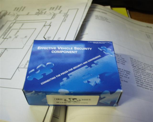
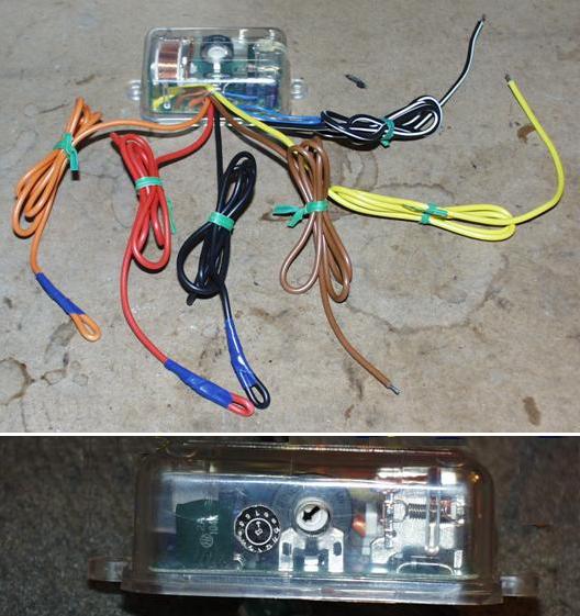
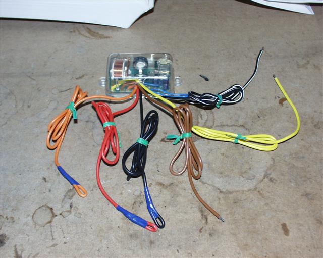
The
DEI D528T pulse timer module.
This unit was bought from
Dr. Detail
Shop. It retails for $29.99 US Dollars.
The box it came in.
Outside of the box
Main items
The
DEI D528T pulse timer module.
Philips screwdriver
10mm Socket wrench with extension
2 Blue Butt Connector
Electrical tape
Optional
flat head screwdriver
additional electrical wire (any color)
Door Trim Removal tool
1 or 2 nylon snap ties
Time to install item:
Total time for mod:
30-90
min
Necessary
pre-mod / install steps.
Before any modification / installation,
1- Write down
any pre-set radio stations you have set your radio too.
2- Then disconnect the negative battery.
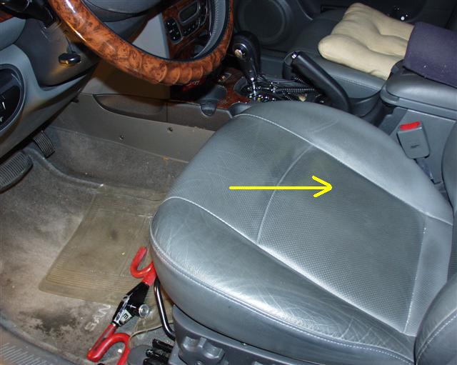
3-
Place the drivers side seat as far back as possible.
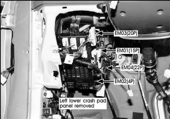
Removing the
necessary panel covers.
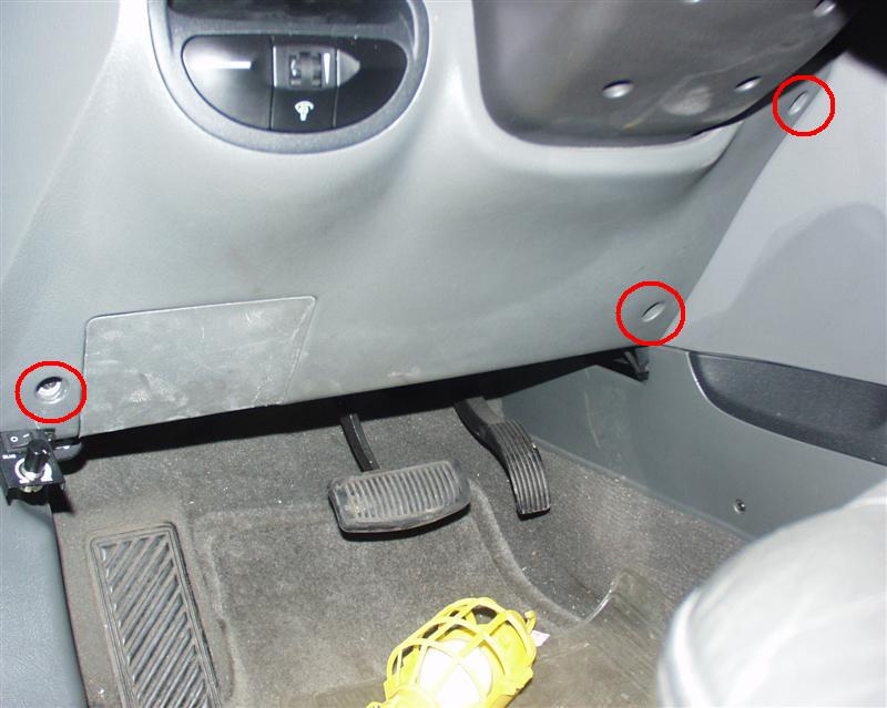
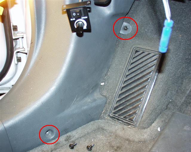
Raise the steering wheel to it up most position.
Remove the 3 screws from the left lower crash pad panel using a Philips
screwdriver.
Gently but firmly unclip the crash pad
panel by pulling it towards you.
Be careful as the Rheostat M11 switch will still be connected to the
Rheostat and you will need to unplug it during the panel removal.
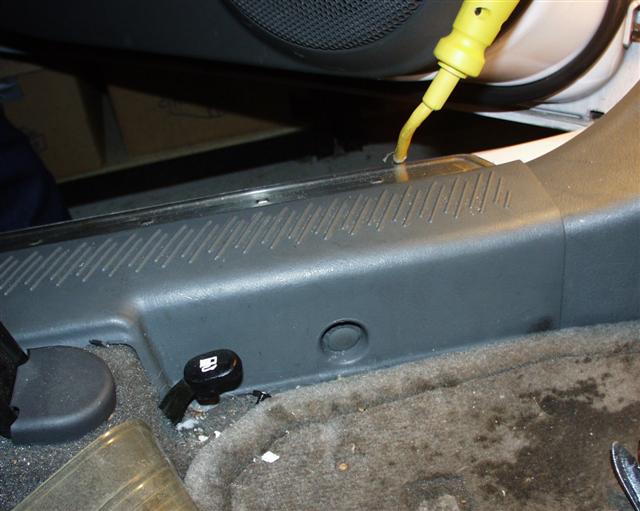
Remove the
drivers side floor sill cover.
Note This is a peg and is a bit hard to take out. Carefully use a flat head
screwdriver or a door trim removal tool to gently pop it out.:
Remove the
lower left side panel.
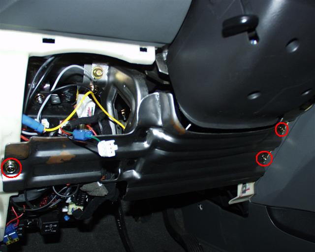
Identifying the
connectors you will be working with.
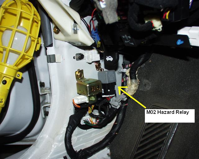
M02 hazard Relay
With the lower left side panel removed, you will see the M02 Hazard Relay
along with the M01 Chime Bell.
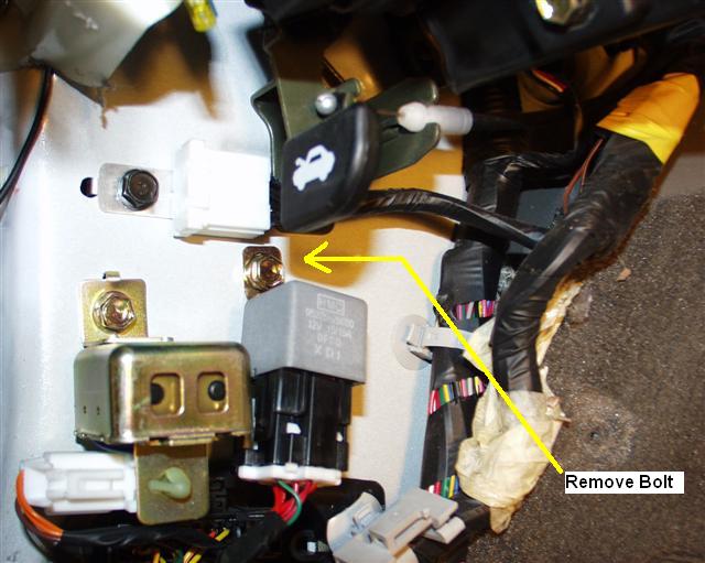
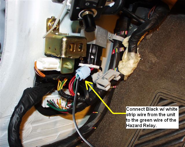
Remove the
bolt holding the M02 Hazard Relay to the chassis.
Pull back on
the electrical tape that covers the wires of the M02 Hazard Relay to expose
the wires. You will be working with the green wire.
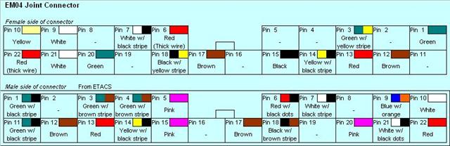
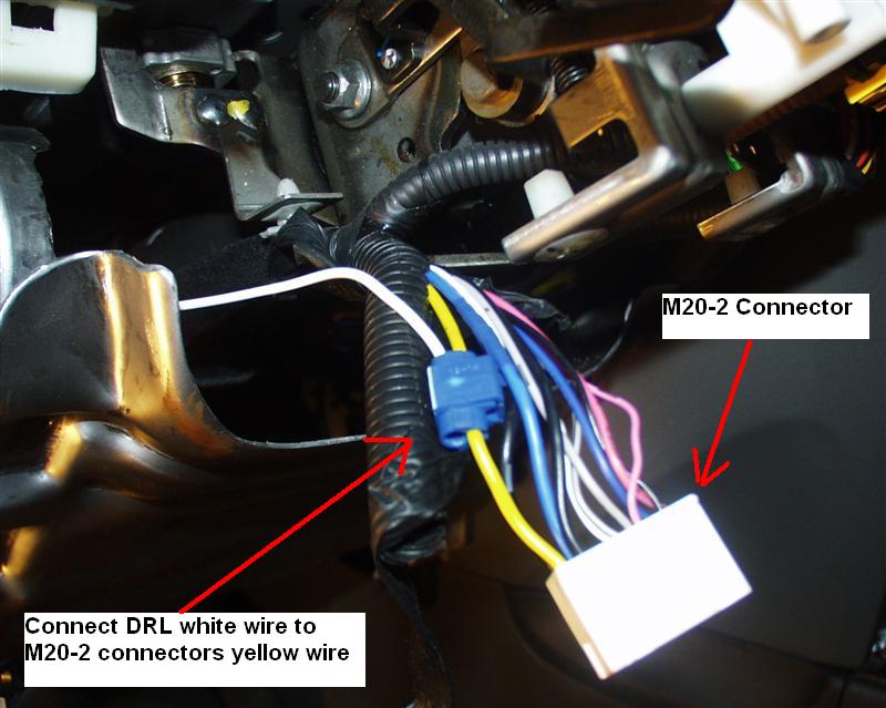
EM04 Joint Connector
The EM04 Joint connector is located to the right of the Passenger
Compartment Junction Box (PCJB).
Optional Step:
Access to the connector is a bit tight since there is a metal crossbar in
front of it. You can get to it but if you feel that there is not enough room
for you to work with then you can take out the metal crossbar by removing
the 5 bolts. (I left it attached).
The EM04 joint connector consists of both a male and female connector, which
is not so easily apparent as to what gender it is. The female connector is
the one that can be unclipped and fits inside the male connector.
Note: Its not the shape of the connector that determines the gender but the
connector pin.
You will be working with the female side of the connector and its the only
one that can be detached. The male side stays connected to the Passenger
Compartment Junction Box.
Disconnect the EM04 Joint connector, (female side). You will notice that it
has 22 pins/wires that lead to/from it. Depending on your model not all
wires will be available.
You
will be working with the Pin # 22 Red wire and the Pin #21 White wire.
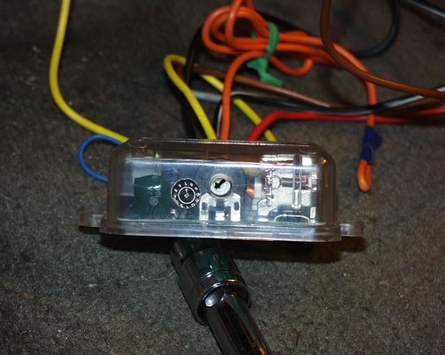
Familiarizing
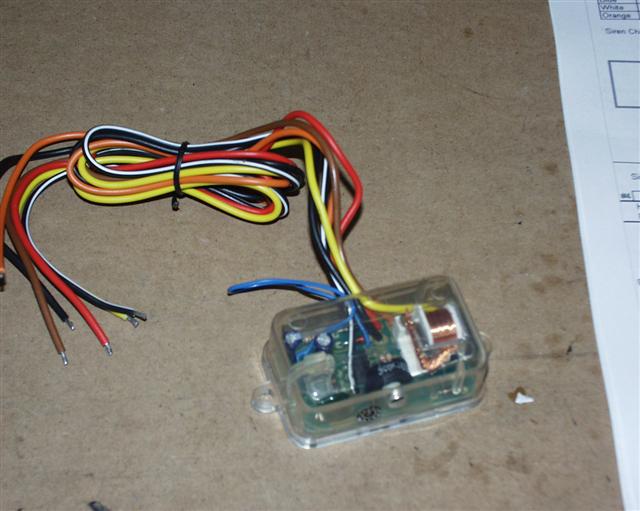
yourself with the D528T Pulse Timer module.
The DEI D528T Pulse Timer is an adjustable timer with a built in 30A relay.
It allows you to disconnect a circuit for a certain amount of time. It has 7
wires leading from it and on the unit itself has an adjustable rotary switch
to adjust the timing sequence of the incoming pulse.
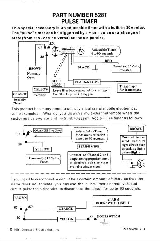
The module
comes with generic instructions, which are not to be followed for this
modification. I am providing the original instructions so you can see what
it looks like.
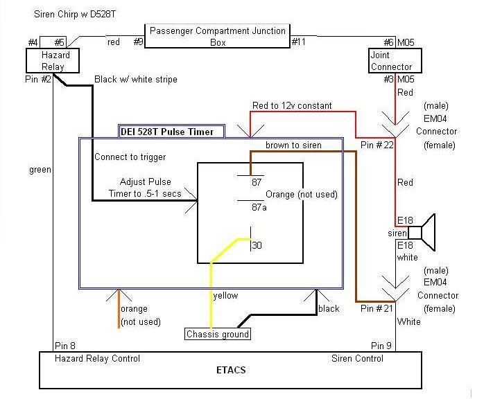
With help from fellow Santa Fe Forum member southpawboston, we were able to come up with the correct way of hooking up
the module. (see below)
Connecting the D528T
Pulse Timer.
The DEI D528T Pulse Timer has 7 wires. Which are as follows...
Color
Connect
to
Wire
Color
Connector
Black w/ white
Stripe
Pin # 2
Green wire
M02 Hazard
Relay
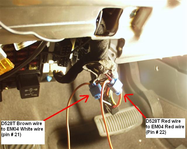
Red
Pin # 22
Red wire
EM04 Connector
Brown
Pin # 21
White wire
EM04 Connector
Black
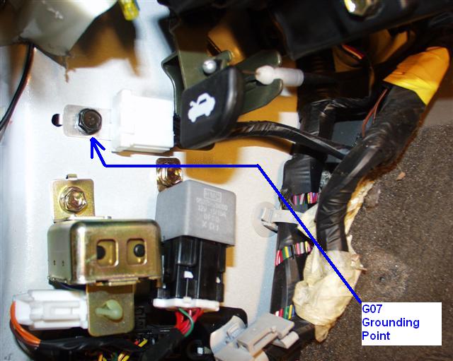
Ground
G07 Ground
point
Yellow
Ground
G07 Ground
point
Orange
Not used
Blue
Not used
Connect the Black w/ white stripe wire from the D528T to the M02 Hazard
Relay Pin # 2 Green wire using a blue butt connector.
Connect both the Black and Yellow wires from the D528T to the G07 Ground
Point that is near to the M02 Hazard Relay.
Using the EM04 diagram above locate the Pin # 22 Red (thick) wire of the
EM04 female connector and connect the Red wire from the D528T to it using a
blue butt connector.
Connect the Brown wire from the D528T to the EM04 Pin # 21 (White wire) also
with a blue butt connector.
The orange wire should be taped up and
electrically secured. The Blue wire is left alone since we are working
with a (-) negative system.
Reattach the EM04 female connector into
the male connector. (This is very important that you do not forget this
step).
Adjusting the timer.
As mentioned
earlier, the D528T Pulse Timer has a built in adjustable rotary switch that
allows you to set the timing sequence to disconnect a circuit a certain
amount of time. I turned the switch counter clockwise using a flat head
screwdriver to the left most position which should be position # 1.
Note: In the testing trials, the only
suitable setting for the chirp timer was at the lowest # 1 setting. Anything
over that would have the siren go off as normal. So trust me leave it at the
lowest setting. You can play with it later.
Testing the D528T
Pulse Timer.
At this point, make sure that you
reattached the EM04 female connector to its male counterpart. Leave the D528T on
the floor of the cabin, close all open doors. Reattached the battery and
test the D528 Pulse Timer using your FOB (remote transmitter).
You should notice the following...
When Arming the vehicle, you should now hear two chirps and the lights flash
twice.
When disarming the vehicle, you should now hear one chirp with on flash of the
lights.
If you do not hear any chirp then recheck your connections. If you hear the
siren then you set the rotary timer switch incorrectly.
If you hear the chirps, congratulations. At
this point you may want to play with the rotary switch, but trust me you will
hear the regular siren if it is not set to the lowest setting.
Notes on the Chirps.
Aside from setting the timer to the lowest
setting possible to hear a chirp as mentioned above, the sound that is produced
is just like any other alarm chirp you hear from other vehicles except that
instead of the usual .05 of a second chirp, it is a bit longer like .75 of a
second. Not that much of a difference but noticeable if you really pay
attention. Either way it is still a recognizable chirp, it works and you no
longer have to turn your head to determine if your alarm has been set.
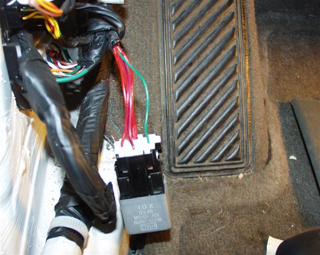
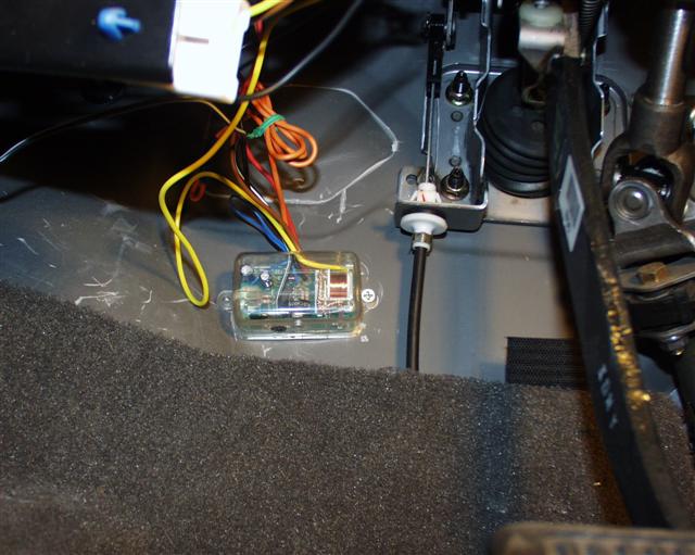
Securing the D528T
Pulse Timer.
At
this point, knowing that the Pulse Timer works, you can wrap up the project by
securing the loose wires by wrapping them up in electrical tape if desired
and secure the module in a place that will be from normal view. I chose to
place it at the back of the drivers foot area up where the clutch would have
been if my Santa FE had a manual clutch on the firewall using a screw.
Final wrap up.
At this point, you can start putting back the lower crash pad
and door sill panels covers in reverse order as mentioned above in the section
"Removing the Necessary Panel Covers". Re-connect the battery and reset your
radio setting.
